How to Calculate the Right Cable Tray Size for Your Project?
May 14, 2026Every cable in your facility sits in a cable tray, and getting the cable tray size right is trickier than it looks.
An undersized tray crowds cables, traps heat, and turns every future addition into a difficult task. Whereas an oversized one wastes material, adds unnecessary load to your structure, and eats into space you could use better elsewhere. Neither is acceptable.
Why Cable Tray Sizing Is Important?
A cable tray is more than a shelf for wires. It's a functional part of your electrical infrastructure, and when it's sized poorly, the consequences ripple outward.
Trays that are too small cause problems like:
- Restricted airflow, leading to heat buildup and eventual insulation damage.
- Difficulty pulling new cables through existing routes during upgrades.
- Non-compliance with safety standards that specify fill limits.
- Increased wear on cable jackets from overcrowding.
How to Choose the Right Cable Tray Dimensions?
Choosing the right cable tray dimensions doesn’t have to be complicated. The key is selecting a tray size that safely supports your current cables while allowing room for future expansion, proper airflow, and easy maintenance. The right dimensions help improve cable management, safety, and overall system efficiency.
Start with What You Know: Your Cable Inventory
Before you even look at tray catalogues, you need a clear picture of what's going on inside. This is the step most people rush through, and it's usually where sizing errors originate.
Pull together:
- The total number of cables for that particular route.
- The outer diameter (OD) of each cable, jacket included.
- Whether each cable is power, control, or instrumentation.
- Any segregation requirements between voltage levels.
An industrial plant with a mix of heavy power cables and thin control wires will need a very different tray arrangement than a commercial building running mostly data and low-voltage lines. Knowing your cable mix upfront shapes every decision that follows.
A General Approach to Sizing:
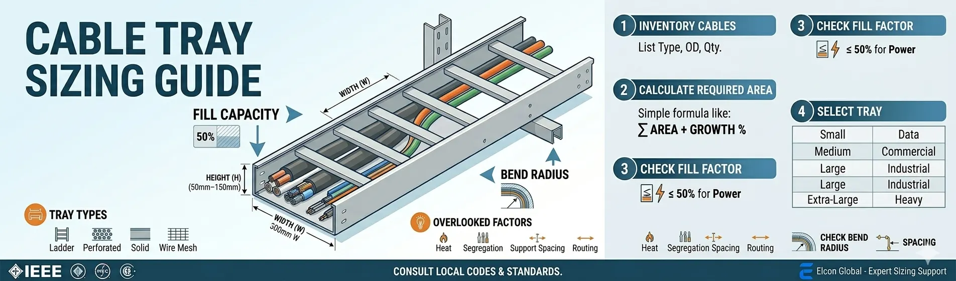
At its core, the sizing process follows a simple sequence.
- Figure out the total space your cables need - Every cable has a cross-sectional area based on its outer diameter. Add those up for all cables on a given route, and you get a total cable area.
- Apply the fill factor - Since you can only use 40 to 50% of the tray's internal area (depending on cable type), divide your total cable area by the appropriate fill percentage. That gives you the minimum usable tray area.
- Match that area to a standard tray size - Trays come in fixed widths and depths. You pick the combination that meets or exceeds your required area, then round up to the next available standard size.
- Add a growth margin - This is the part most projects skip, and it almost always comes back to bite them. A 20 to 40% spare capacity buffer is considered good practice across most industries.
The specifics change from project to project, but the thinking stays the same.
Standard Cable Tray Sizes You'll Encounter:
One thing that makes the selection process easier is that cable tray sizes in mm are fairly well standardised across manufacturers, especially for industrial-grade trays.
- Standard cable tray widths you'll commonly find in the market start at 50 mm and go up through 100, 150, 200, 300, 450, 600, 750, all the way to 900 mm.
- Standard depths usually come in 50 mm, 75 mm, 100 mm, and 150 mm, though a few manufacturers do stock 200 mm options for projects with heavier cable density.
- Standard lengths are usually 2 metres, 3 metres, or 6 metres per section.
Here's a quick reference for how these sizes typically map to applications:
| Width (mm) | Depth (mm) | Typical Use |
|---|---|---|
| 50 to 100 | 50 | Light data or control cabling. |
| 150 to 300 | 75 to 100 | Mixed cable routing, commercial buildings. |
| 450 to 600 | 100 to 150 | Power distribution, industrial plants. |
| 750 to 900 | 150 | Heavy industrial, petrochemical, and large power runs. |
Keep in mind that this cable tray size list serves as a general reference. Your project's actual requirements could fall between these, and that's where a manufacturer's engineering support becomes valuable.
How Cable Tray Type Affects Your Size Decision?
You can't separate size from type. The style of tray you choose directly influences how much cable it can practically hold, even at the same nominal dimensions.
- 1. Ladder cable trays are the go-to for heavy power cables. Because of their open-rung design, heat escapes naturally rather than getting trapped around the cables. That's a real advantage when you're working close to your fill limit. They're commonly used in refineries, power plants, and large manufacturing facilities.
- 2. Perforated cable trays sit somewhere in the middle. The slotted base offers decent ventilation while providing more continuous support than a ladder tray. They work well for control cables, medium-voltage runs, and mixed routing.
- 3. Solid bottom trays give the most physical protection, shielding cables from dust, debris, and chemical exposure. But that enclosed design limits airflow, which means you may need to derate your fill percentage or choose a wider tray to compensate for reduced cooling.
- 4. Wire mesh trays are lightweight, flexible, and popular in data centres and IT environments. They're easy to cut and adapt on site, but they're not built for heavy loads. Best suited for fibre optic, Ethernet, and other low-voltage, low-weight cables.
Material selection plays a big role here as well.
- Stainless steel, for instance, is the preferred choice wherever corrosion is a real threat, think coastal facilities with constant salt air exposure or chemical plants where aggressive fumes are part of daily operations.
- Hot-dip galvanised steel offers durability at a lower cost for most indoor industrial settings.
- Aluminium keeps weight down where structural load is a concern.
Each material choice can subtly affect the internal usable space due to differences in wall thickness and coating layers.
Factors People Overlook When Choosing Cable Tray Dimensions:
Getting the width and depth right on paper is only part of the story. Several real-world factors regularly influence (and sometimes override) calculated sizing.
- 1] Heat management - More cables packed together means more heat. Ladder trays handle this naturally. Solid trays may require wider sizing or forced ventilation in some installations.
- 2] Cable segregation - Power, control, and communication cables often can't share the same tray. Voltage separation requirements might mean you need two or three smaller trays instead of one large one.
- 3] Support spacing - Wider, heavier trays need stronger and more frequent supports. A 900 mm tray loaded with power cables will need support brackets at tighter intervals (typically 1.5 to 2 metres) compared to a lightly loaded 150 mm tray that can span 3 metres.
- 4] Routing constraints - Ceiling clearance, corridor width, beam locations, and existing services all play a role. Sometimes the "right" calculated size simply won't fit in the space available, and you need to rethink the layout or split routes.
- 5] Coating thickness - This one's easy to miss. A hot-dip galvanised finish or an anti-corrosion coating adds a thin layer to the tray walls. On a 100 mm tray, the difference might feel negligible. On a narrow tray already close to its fill limit, it can matter.
How Elcon Global Supports Smarter Cable Tray Sizing?
Choosing the right cable tray size isn't just about picking numbers from a chart. It's about matching those numbers to what your cables actually demand, what your environment throws at them, what your facility might look like five or ten years from now, and which codes and standards apply to your installation.
This is where Elcon Global comes in.
As a leading cable tray manufacturer, Elcon Global brings to the table:
- A full range of standard cable tray sizes, along with custom configurations across every major tray type.
- Engineering support to help you match cable tray dimensions with real project requirements.
- Material options built for longevity, including stainless steel, hot-dip galvanised steel, and aluminium.
- Guidance on fill capacity, load ratings, and compliance with NEC and IEC standards.
The goal is to make sure the tray you install works reliably for the life of your facility, handles whatever changes come along, and keeps your installation inspection-ready from day one.
Conclusion:
Picking the right cable tray size comes down to knowing your cables, respecting fill limits, choosing the right tray type for your environment, and leaving room for the future. It's not glamorous work, but it's the kind of decision that separates installations that last from ones that create headaches down the road.
Need help picking the right cable tray size for your project? Get in touch with us for expert sizing support and a product range built to match your exact requirements.
FAQs:
1] How to calculate cable tray sizes?
Add up the cross-sectional area of all cables on a route, apply the applicable fill factor (typically 40 to 50%), and select a standard tray width and depth that accommodates the resulting area plus a growth margin.
2] What is the formula for calculating cable length?
Cable length is determined by tracing the full routing path, including horizontal runs, vertical drops, bends, and adding extra length for terminations at both ends.
3] What is cable tray fill capacity?
It refers to the maximum percentage of a tray's internal cross-sectional area that can be occupied by cables, set by safety codes to ensure proper ventilation and heat dissipation.
4] What fill percentage should be used for cable trays?
Most installations follow 40% for power cables and up to 50% for control or instrumentation cables, as specified under NEC Article 392 and IEC 61537.
5] What standards govern cable tray sizing?
The primary standards are NEC Article 392 (in North America), NEMA VE 1 for cable tray design and load capacity, and IEC 61537 for international cable management systems.
6] How do you calculate tray width from cable diameter?
Calculate total cable area using outer diameters, divide by the allowed fill percentage, then divide the result by tray depth to arrive at the minimum required width, rounding up to the nearest standard size.